Established in 2016. Find out more about our journey.
Fogstar Energy
ESR51.2 Quick Start Guide
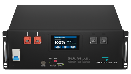
Our SR51.2V Rack Battery is the ideal solution for medium to large scale home, and commercial, off-grid and on-grid energy storage systems. They can also be used for mobile energy, telecoms and back-up energy installations.
The 16 cell EVE LF100LA (161SP) configuration offers an industry leading 4000 cycles @ 80% DOD, and is paired with a premium 100A Pace BMS.
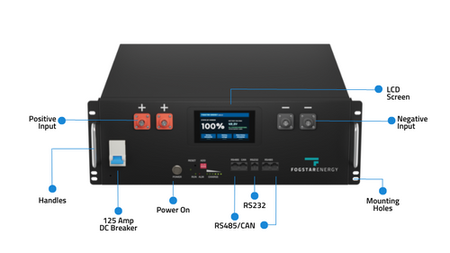
The 3.5U unit features RS485 and CAN inputs, 125 Amp DC Breaker and ‘out of the box’ preloaded inverter protocols for Victron, Pylontech, Growatt, Solis and Goodwe.
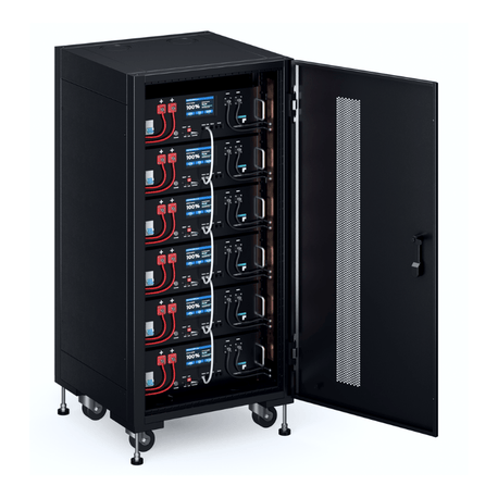
Up to 16 racks can be connected in parallel (offering up to 81.9kWh of power). However we must note, you cannot connect the Fogstar Energy SR51.2V Server Rack Battery in series.
About this Manual
This manual is intended to give you a brief overview of the steps required to set-up your battery, cabinet and connect the Fogstar Rack Battery to your inverter.
Installation takes approximately 20-30 minutes for 6 racks and a cabinet.
1. Setting up your cabinet, unboxing your battery and installing racks into the cabinet.
2. Installing battery cables and completing the battery assembly.
3. Connecting battery to PC.
4. Changing inverter protocol via BMS software.
Health and Safety Information
Wear proper safety gear such as gloves and eye protection
These batteries are HEAVY (45kg) - always get help to lift them
Do NOT lift or move these batteries in the Fogstar Rack Cabinets - they are likely to topple
Ground your cabinets before you insert your rack battery
Do not reverse polarity
Do not connect with any batteries in series
Ensure the system is properly grounded
Always use insulated tools
Do not work on battery with it turned on or with the grid turned on
Do not connect battery to solar wiring directly
Make sure all fasteners are properly torqued
Ensure your chargers/inverters are appropriately programmed
Use only on 48v nominal systems, do not connect with other batteries (such as 15s)
Ensure the installation follows applicable local, national and all legal electric stipulations
Installation should be done by a qualified and knowledgeable person
Make sure proper cable sizes and overcurrent protection are utilised
Ensure the system is installed in a location suitable for electronics
Keep the battery within safe operational temperatures
Do not put the battery in a hazardous, hot or flammable environment
Install your equipment in a location where children and pets are not present
Do not paint, or spray paint the battery
If there are any electrical smells or excessive heat, use your breaker switch and contact your local fire station
Only clean the battery with a dry cloth - do not use any liquids, spray cleaners, aerosols or any type of solvents.
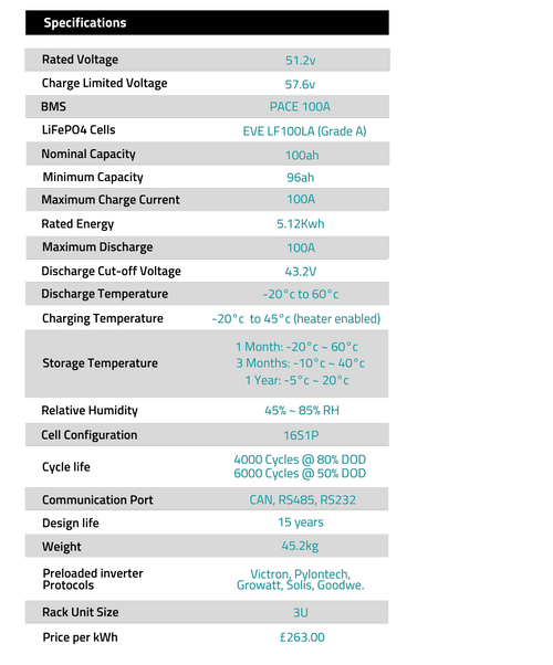
Battery Specifications
Packing List
Fogstar ESR51.2V 5.12KWH Rack Battery
PC communication cable RS232 to USB
One Battery to Battery (B2B) communication cable (RS485 to RS485)
x2 Positive 8AWG cables
x2 Negative 8AWG cables
USB loaded with programmatic
BMS software.
About your Fogstar ESR51.2V 5.12KWH Rack Battery
1. Setting up your cabinet, unboxing your battery and installing racks into the cabinet.
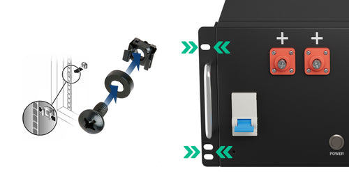
1a. Your battery and cabinet will arrive on a pallet, and they are heavy! (the battery is 48KG and the cabinet is 20kg). Please ensure you grab a friend or family member to help you. Your empty cabinet can be rolled into place, and secured using the extendable legs.
1b. The cabinet can be opened by pressing the key hole on the handle. This then releases the handle so you can gain access. Each cabinet comes with two sets of keys. Please remove these from inside the cabinet, and keep them safe. It is best practice to lock the cabinet if children and animals are present.
1c. Once you are happy that the cabinet is secure, you can slide your first battery into one of the shelving units inside the cabinet. You can then fix the batteries, by using the black M6 bolts & washers. Continue to do this for all the batteries in your system, securing them with the bolts and washers as you go.
2. Installing battery cables and completing the battery assembly.
Please make sure that the battery is OFF and the BREAKER on the battery is in the OFF (DOWN) position before progressing.
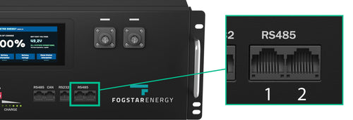
2a. Connecting RS485 Battery Linking Cables
This diagram presumes that your main battery will be your top most battery in the cabinet.
The diagram below shows the RS485 Linking cable ports. The left port (number 1) connects to the next battery (sending communication). The right port (number 2) receives the connection from the previous battery (receiving communication).
The main battery at the top should only have one RS485 linking cable in the right port. Your bottom battery should only have one RS485 in the left port. All middle batteries should have cables connected to both.
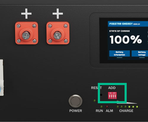
2b. Configuring DIP Switches
Now your batteries can communicate with each other, we need to tell them where they are in the order of things (at the moment they all think they are battery number 1).
We can do this via adjusting the DIP switch. These are the red and white 'ADD' switches as per the picture on the right.
2c. Connecting the Positive and Negative Busbar cables
We can now connect the negative busbar cables. The cables we provide connect both negative terminals on the battery (M8 bolts) to the negative busbar of the cabinet with an M10 bolt.
Connect all negative leads first. We recommend leaving one M10 bolt free on the BOTTOM of the busbar to attach the negative inverter cable.
We can now connect the positive busbar cables the same way, but onto the positive busbar of the cabinet. We recommend leaving one M10 bolt free on the TOP of the bus bar to attach the positive inverter cable.
2d. Connecting Inverter Cable Positive and Negative.
Connect the negative inverter cable to the bottom of the negative busbar using one of the spare M10 bolts in the busbar, and the positive inverter cable to the top of the positive busbar.
You can run both of these cables out of the top or bottom of the cabinet through the cable exit holes.
This stage will vary depending on your inverter manufacturer. Please consult the manual of your inverter manufacturer for more in depth details. Most inverters will have a positive, negative and ground connection on the bottom for the battery bank.
You can now turn ON all your batteries with the POWER button, however you DC BREAKER should remain in the OFF position.
3. Connecting battery to PC and using BMS software.
The battery can be connected to a PC by using the included RS232 to USB cable. This requires a windows PC and has been tested on Windows 7 and above.
On the initial connection to the USB port, Windows will automatically download drivers for the USB to RS232.
Download the PBMS BMS monitoring program from here.
You may be asked to install or update Microsoft .Net Framework, please proceed with this.
Open the PBMS Monitoring Tool.

4. Changing inverter protocol via BMS software.
PbmsTools has plenty of powerful features, however we are just focusing on changing the inverter protocol for now.
1. Open the Realtime Monitoring Tab and select connect under the Serial Port section.
2. Select the System Config Tab. Under the Inverter Protocol section, click READ. This will read all inverter protocols currently on the BMS.
3. You can now change CAN and RS485 inverter protocols by selecting which one you require, and then pressing WRITE.


